
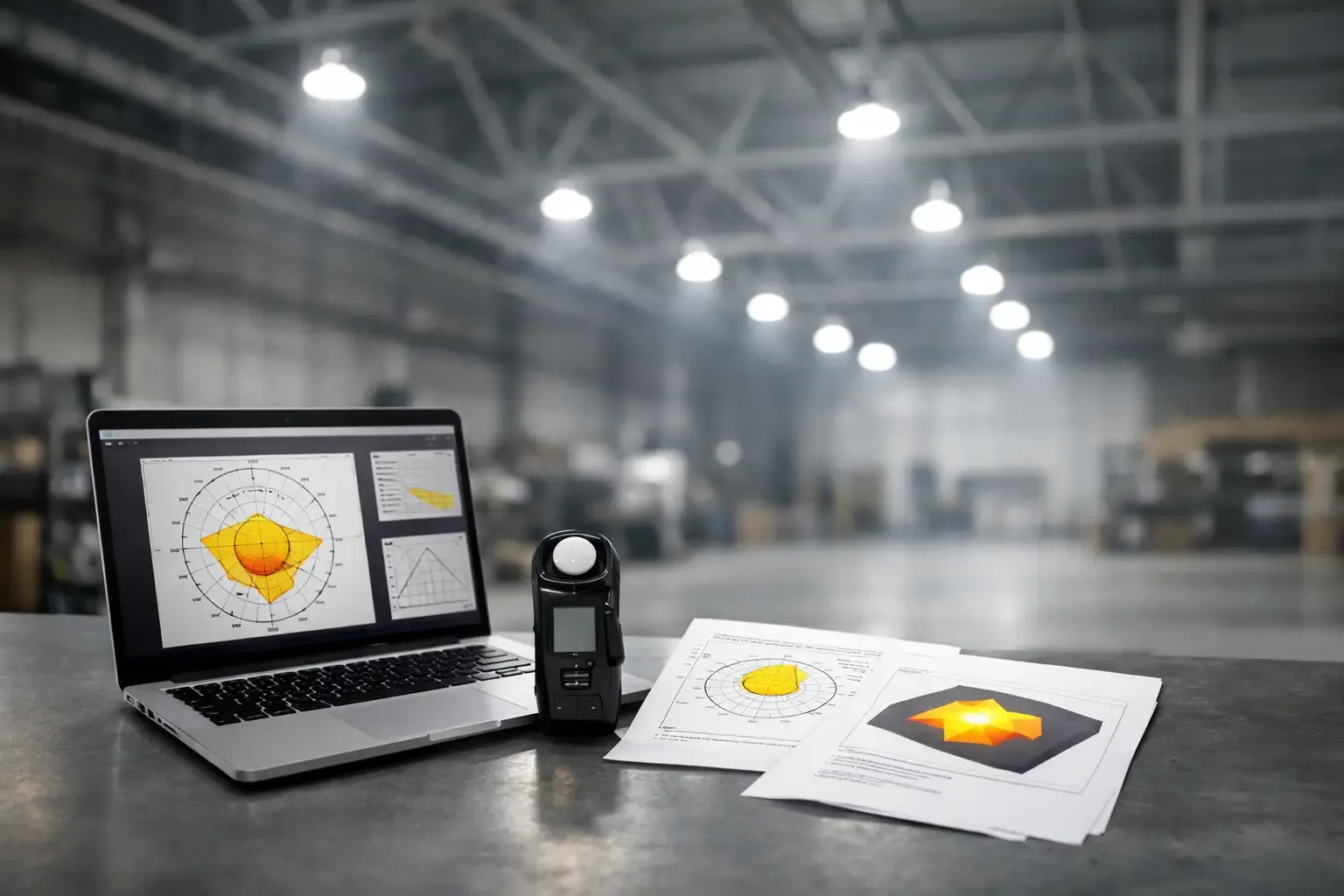
A fixture can have the right hazardous-location rating, voltage, and housing material yet still perform poorly if its photometric distribution is wrong for the space. Knowing how to read IES files helps engineers, contractors, and facility teams verify where a luminaire puts its light before it is installed over a process line, loading area, aisle, or washdown room.
For fixture-specific photometric files, layout support, and application review, contact Maes Lighting before finalizing a lighting package. This is particularly useful when selecting explosion-proof, vapor-tight, high-temperature, marine, NSF, or IP69K lighting, where mounting restrictions and operating conditions can materially affect the final illumination results.
What an IES File Actually Tells You
An IES file is a standardized digital photometric report, commonly provided in IES LM-63 format. It describes the measured light output and distribution of a specific fixture configuration. Lighting design software uses this data to calculate foot-candle levels, uniformity, glare, and spill light across a modeled area.
The file does not prove that a fixture is suitable for a hazardous location, food-processing washdown area, or corrosive marine environment. Those decisions require separate review of listings, certifications, ingress protection, temperature ratings, construction materials, and site conditions. Think of the IES file as performance data, not a compliance certificate.
For industrial projects, the most useful question is rarely "How many lumens does this fixture produce?" It is "How much light reaches the work plane, at the required uniformity, from the available mounting location?" An IES file provides the distribution data needed to answer that question.
How to Read IES Files: Start With the Header
Open an IES file in a text editor and the first section may look technical. Most project teams instead view it in photometric software, but understanding the header helps identify whether the data belongs to the exact product being specified.
Look first for the manufacturer name, catalog number, lamp or LED description, and total lumens. Confirm the file matches the selected fixture, not merely the same housing family. A change in optic, wattage, color temperature, lens, reflector, or mounting orientation can alter the distribution substantially.
The header may also identify the test laboratory, testing report number, and file date. These details matter during submittal review, especially when the design team needs traceable documentation. If a file lacks a clear catalog reference or does not reflect the final configuration, request a current photometric file rather than making assumptions.
Lumens are only the starting point
Total lumens describe the quantity of light leaving the fixture. They do not describe direction. Two 20,000-lumen high bays can produce very different results: one may create a broad distribution for lower mounting heights, while another may concentrate light into a narrower pattern for taller ceilings.
Lumens are also not the same as delivered foot-candles. Dirt accumulation, ambient temperature, mounting height, obstructions, surface reflectance, and fixture spacing all affect the illumination that reaches equipment, floors, and work surfaces.
Read the Candela Values to Understand Direction
The core of an IES file is its candela data. Candela is luminous intensity in a particular direction. The file reports values at vertical angles and horizontal angles around the fixture, creating a three-dimensional description of its light pattern.
Vertical angles generally run from 0 degrees straight down from the fixture to 90 degrees horizontally outward. Values beyond 90 degrees indicate uplight, which may be intentional in certain luminaires but is usually limited in enclosed industrial high bays and task-oriented fixtures. The highest candela values show where the fixture concentrates its output.
Horizontal angles show whether the pattern is symmetrical or asymmetrical. A symmetrical high bay often produces similar candela values in all horizontal directions. An asymmetric floodlight, wall pack, or aisle fixture may throw light farther in one direction than another. That is useful when illuminating a rack aisle, perimeter, tank farm path, or loading dock without wasting output behind the fixture.
A quick practical read is to compare the intensity at 0, 30, 45, 60, and 90 degrees. Strong output near 0 degrees usually indicates a more focused downward pattern. Higher values at 45 to 60 degrees can help achieve wider spacing, but they can also increase glare or light on vertical surfaces. Neither pattern is automatically better. The correct choice depends on mounting height, required lighting levels, and the geometry of the work area.
Use the Polar Plot for a Faster Visual Check
Most photometric viewers display a polar chart that turns candela values into a recognizable shape. A narrow, elongated pattern generally indicates a concentrated beam. A broad, rounded pattern indicates a wider distribution. An asymmetric shape reveals directional throw.
This visual check is valuable, but it should not replace a layout calculation. A broad pattern may look suitable until the fixture is mounted beneath roof trusses, ducts, cranes, or cable trays that create shadows. A narrow pattern may appear restrictive but be exactly what is needed for a 40-foot mounting height over a production floor.
For floodlighting, verify the aiming orientation used in the file and in the layout. Rotating an asymmetric optic by 90 degrees changes the result. For linear vapor-tight fixtures, confirm whether the photometric file assumes a lengthwise or crosswise mounting direction. Small orientation errors can create significant dark zones between aisles or over equipment.
Check the Geometry and Field Dimensions
IES files include physical dimensions, luminous opening dimensions, and photometric type. These entries help software model the fixture as a realistic light source rather than a point of light.
Geometry becomes more important when fixtures are mounted close to a work plane or when glare control is a concern. A large luminous surface with lower brightness may be more comfortable than a compact source with intense visible LEDs, even if both fixtures produce similar calculated foot-candles.
Do not confuse a fixture's housing dimensions with its luminous dimensions. The latter describe the portion of the luminaire emitting light and influence the calculation. In industrial applications, also verify the actual mounting bracket, pendant, yoke, or ceiling mount. The fixture's position and tilt can matter as much as its photometric pattern.
Translate Photometry Into a Layout Decision
An IES file is most useful after it is placed into a model of the actual facility. The model should include ceiling height, mounting height, fixture locations, work-plane height, room boundaries, and meaningful obstructions. A basic open-room calculation can be helpful for budgeting, but it may not be sufficient for a facility with racks, machinery, piping, conveyors, or structural steel.
Review average foot-candles, minimum foot-candles, and uniformity together. An acceptable average can conceal low-light areas that affect inspection tasks, forklift travel, housekeeping, or emergency response. Conversely, pushing for maximum uniformity can require additional fixtures and may not be necessary in every storage or circulation area.
Use the actual task to guide the target. General warehouse circulation, detailed assembly, food inspection, equipment maintenance, and exterior security all have different illumination needs. Surface reflectance also matters. A bright painted ceiling and clean floor support more effective distribution than dark, dusty, or heavily stained surfaces.
Consider the operating environment before approving results
Photometric software is not a substitute for environmental engineering. In a food facility, washdown procedures may require NSF-listed or IP69K-rated equipment, and lens selection can affect both cleanability and light distribution. In a refinery or grain-handling area, hazardous-location classification determines whether an explosion-proof fixture is required. In a furnace area, ambient temperature limits may narrow the viable fixture options before photometry is even considered.
Maintenance factors deserve the same attention. Vapor, oil mist, dust, and residue on lenses reduce delivered light over time. A design that barely meets the target when new may fall below requirements between cleaning cycles. Specify a realistic light loss factor and select fixtures that are practical to maintain in the operating environment.
Verify the Documentation Package
Before purchase, match the IES file to the fixture datasheet, catalog number, voltage, optic, mounting method, and required certifications. This prevents a common submittal issue: photometry from a standard commercial version paired with a hazardous-duty or washdown-rated fixture that uses a different lens or optic.
For projects with domestic-preference requirements, documentation must be reviewed separately from the IES file. Maes Lighting can provide Buy America Act support for the Explosion Proof IR1, IR3, IR4, and IR7 series, as well as CIT vapor-tight models. Confirm the applicable project requirement and required documentation early, because domestic-content rules, product eligibility, and submittal language can vary by funding source and contract.
A good lighting calculation should give the project team confidence, not just a favorable average foot-candle number. When the IES file, fixture construction, certifications, mounting plan, and operating environment all align, the result is a lighting package built for safe operation and reliable approval.