
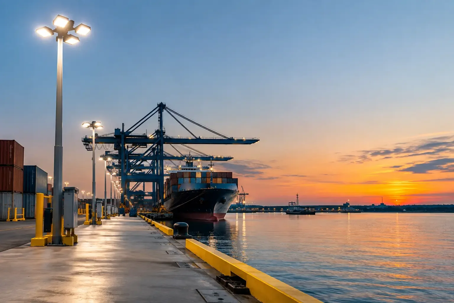
A marine terminal retrofit is rarely driven by lighting alone. It usually begins after corrosion has compromised housings, failed fixtures have created dark work zones, or maintenance crews are spending too much time accessing lights over water, pipe racks, conveyors, and loading berths. The correct response is not simply to replace existing wattages with LED equivalents. It is to reassess the environment, the electrical classification, the mounting condition, and the maintenance plan before a fixture schedule is issued.
At Maes Lighting, we have found that the difficult part of a terminal lighting retrofit is often identifying the true exposure conditions. A fixture mounted under a canopy may appear protected, yet still experience wind-driven salt spray, diesel residue, vibration from cargo handling equipment, and condensation inside junction boxes. A luminaire that performs well in a warehouse can fail quickly at a berth because its seals, coating system, cable entries, or mounting hardware were not selected for marine service.
Start the Marine Terminal Retrofit With Conditions, Not Fixture Watts
The first question is not, “How many lumens are needed?” It is, “What does this fixture have to survive?” Terminal operators should document conditions by area: open dock, vessel manifold, pipe rack, tank farm perimeter, enclosed pump room, crane structure, maintenance shop, and access roadway. These areas may require very different luminaires even when the target foot-candle levels are similar.
Salt exposure is a primary concern, but it is not the only one. Temperature swings draw moisture into marginal enclosures. Crane and conveyor structures transmit vibration that can loosen mounts and cable fittings. Cleaning chemicals, fuel mist, and airborne particulates can attack gaskets and finishes. At active berths, glare control matters because operators need to distinguish hose connections, ladder rungs, deck edges, and hand signals without looking into an exposed high-output source.
A useful site survey records the existing fixture type, mounting height, voltage, circuiting, branch wiring condition, aiming direction, access method, and visible corrosion. It should also record what has failed and where. Repeated failures on one side of a pier can indicate prevailing weather exposure. Failures concentrated near a transfer point may suggest vibration, hazardous-location misapplication, or contamination rather than a basic product defect.
Verify the hazardous-location boundary
Many marine facilities include classified areas around fuel transfer systems, vapor-release points, pumps, and tank connections. Those boundaries must be established by the facility’s electrical area-classification documentation and the authority having jurisdiction, not by visual judgment in the field.
Under the National Electrical Code, Class I locations concern flammable gases or vapors, while Class II locations concern combustible dust. Division 1 and Division 2 describe how likely the hazardous material is to be present in ignitable concentrations. Zone classifications may also be used where the installation is designed under that system. The fixture marking must match the actual classified location, gas group, temperature code, and installation method.
“Explosion-proof” is not a general synonym for durable. It describes equipment construction and listing suitability for specified hazardous conditions. Installing an ordinary marine-rated floodlight in a classified vapor area can create a compliance and safety problem even if the housing appears heavily built. Conversely, specifying an explosion-proof fixture throughout an unclassified terminal can add cost, weight, and maintenance complexity without improving the installation where it counts.
Review the fixture’s certification documentation early. Listings or evaluations from organizations such as UL or Intertek should be traceable to the exact catalog configuration, including voltage, mounting style, cable entry arrangement, and hazardous-location marking. A submittal package should also include photometric files, dimensional drawings, installation instructions, and ambient-temperature limitations.
Select Marine Luminaires for Corrosion and Access
A terminal retrofit should treat the luminaire, mounting arm, fasteners, junction box, and wiring entry as one system. A high-quality fixture can still be undermined by carbon-steel hardware, incompatible metals, poorly sealed conduit hubs, or a mounting position that traps standing water.
Marine-capable lighting typically needs a corrosion-resistant housing, durable protective finish, gasketed construction, and an ingress-protection rating appropriate to direct weather and washdown exposure. IP ratings help describe protection against solids and water ingress, but they do not replace a review of salt fog performance, material compatibility, vibration resistance, and hazardous-location certification where required.
For open berths and exposed platforms, fixture geometry matters. Smooth, drainable surfaces reduce places where salt deposits and moisture can collect. Hardware should resist corrosion and be selected with galvanic compatibility in mind. Where stainless components are used near aluminum housings or structural steel, the mounting detail should be evaluated for the site’s wet, conductive salt environment.
Maintenance access deserves the same attention as fixture output. A 150-foot mast may deliver broad coverage, but every failure can require specialized access equipment, dock coordination, and work restrictions near vessel activity. In some retrofits, adding lower-mounted, targeted luminaires at stairs, valves, gangways, and hose-handling zones improves task visibility while reducing dependence on high-mast fixtures.
Use Photometrics to Protect Work, Not Just Meet an Average
Average foot-candle calculations can hide poor conditions at the places where workers make decisions. A berth may meet an average target while still having deep shadows below pipe racks, glare at the gangway, and inadequate vertical illumination on valves, labels, and emergency equipment.
Photometric modeling should account for mounting heights, obstructions, structural shadows, vessel-side reflections, and the orientation of operator sightlines. Horizontal illumination is necessary for walking and equipment movement, but vertical illumination often determines whether an operator can read a gauge, identify a coupling, or see a coworker’s hand signal.
LED retrofits can reduce energy use substantially, but lower wattage should be the result of sound optical design, not the only project objective. A narrow-beam floodlight may create high readings directly under the fixture and leave adjacent service areas dark. A broader distribution may reduce peak readings but produce better uniformity and safer transitions between bright and dim areas.
Color quality also has a practical role. Moderate correlated color temperature and adequate color rendering can improve recognition of markings, labels, leaks, and safety colors. The right choice depends on site preferences, camera systems, operating hours, and the visual tasks performed at each location.
Plan Installation Around Uptime and Existing Infrastructure
Terminal operations rarely allow unrestricted outage windows. A retrofit plan should identify which circuits can be isolated, which locations require marine access or lift equipment, and whether temporary lighting is needed for safe work. The installation sequence may be more valuable than a small reduction in fixture cost.
Before ordering, confirm voltage, branch-circuit capacity, conductor condition, conduit fill, grounding, and control compatibility. LED drivers can reduce steady-state load, but inrush current, surge exposure, and control interfaces still need review. Facilities using photocells, contactors, lighting panels, or networked controls should verify that the proposed drivers and control strategy will operate reliably in the application.
Surge protection is particularly relevant at marine sites with long runs, exposed structures, switching loads, and weather-related electrical disturbances. It should be considered at both fixture and distribution levels based on the electrical design. For critical routes, separate circuits and sensible zoning can prevent one failure from taking an entire berth or access corridor dark.
Commissioning should include more than turning fixtures on. Verify aiming after dark, check for glare from normal operator positions, inspect gasket compression and cable entries, confirm mounting torque, and document fixture locations and circuit assignments. This record makes future maintenance faster and provides a useful baseline when conditions change.
Avoid the Common Retrofit Shortcuts
The most costly mistakes are usually specification shortcuts. Reusing a legacy mounting arrangement without inspecting corrosion can put a new fixture on a weakened support. Selecting by lumen package alone can create glare, uneven coverage, or excessive maintenance exposure. Treating a marine rating as a substitute for hazardous-location approval can create a code issue that stops the project late in review.
Another common problem is incomplete documentation. Contractors and facility teams need more than a product photograph and a nominal wattage. They need listing information, photometrics, installation details, environmental ratings, and a clear bill of materials that identifies the exact mounting and entry accessories. That documentation reduces field substitutions and prevents delays when the project reaches engineering review or inspection.
A well-planned marine terminal retrofit makes night work more visible, maintenance more predictable, and hazardous-area decisions easier to defend. Start with the locations that expose workers and equipment to the greatest risk, then select lighting around the actual operating environment rather than the fixture that happens to fit the old mounting hole.